Vacuum Conveying System Design Calculation
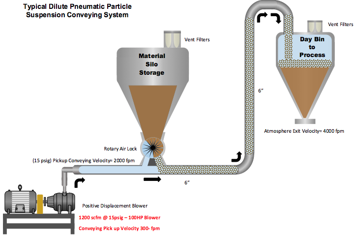
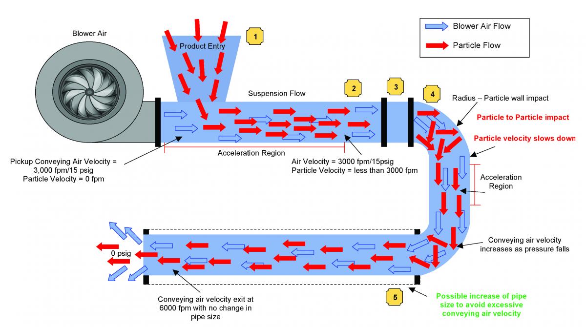
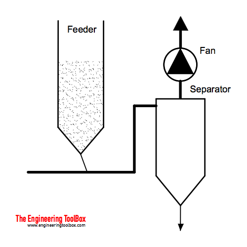
Vacuum conveying system design calculation. The existing system has 6 inch ID pipes and is configured as shown in the diagram below. This economical method of materials handling is compact and versatile offering good scope for handling a wide variety of products and applications. Of the conveying system.
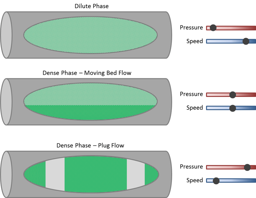
DESIGN EXAMPLE DILUTE PHASE PNEUMATIC CONVEYING A plastics production plant wants to increase the capacity through an existing conveying system. In the area of food processing the pharmaceutical and chemical industry and for material feed in plastics processing suction conveying is indispensable when powder or granular materials have to be transported. In vacuum- and pressure pneumatic conveying calculations the used product properties are identical.
Vacuum Calculations Page 5 System Design. Of course for accurate vacuum system calculation the right information needs to be fed into the simulation exercise. This article presented an understanding of what vacuum conveyors are and their types designs and uses to help understand how to create an effective vacuum conveying system.
The calculation result should be the capacity at a certain pressure drop. However both these values are not known. System dimensions leak-rates gas throughputs construction materials vapourgas to be pumped target pressures internal fixture design hazardous substances involved there are a plethora of things that need to be considered and accounted.
Ad Ideal way to convey high volumes of material over long distances. With typical conveying distances of less than 300 feet and line sizes of up to 6 diameter. A leak in a pressure conveying system will quickly result in a dust cloud in the plant a primary.
Phenomenon and design vacuum vessels to be sturdy enough to withstand the external atmospheric pressure of 147 pounds per square inch at sea level in the absence of compensating internal pressure. It differs from hydraulic or slurry conveying in that the gas expands continuously along the pipe length. Steel sheets stacked on a pallet.
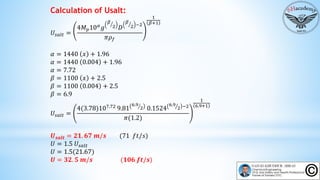
I would be very appreciate if someone can give me some instruction on that issue. Rameters is the minimum conveying air velocity necessary to convey a material.
Of course for accurate vacuum system calculation the right information needs to be fed into the simulation exercise.
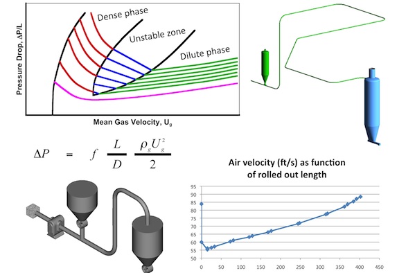
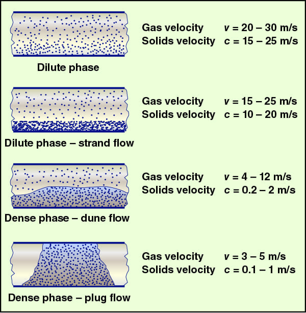
In vacuum- and pressure pneumatic conveying calculations the used product properties are identical. Ad Ideal way to convey high volumes of material over long distances. This economical method of materials handling is compact and versatile offering good scope for handling a wide variety of products and applications. The calculations for the design of a dilute phase conveying sys-tem are based on determining the pressure drop that is gener-ated in the system due to the flow of gas and solids. These systems are versatile and adaptable for different materials and the low operating pressures allow lower cost pipelines and fittings. Higher-bulk- density materials require faster transport velocity. The lean phase system is easy to use maintain and clean making turn-around times. The calculation result should be the capacity at a certain pressure drop. Available in threaded and heavy duty versions.
The existing system has 6 inch ID pipes and is configured as shown in the diagram below. Models available for hygienic applications. Pneumatic conveying is the movement of solids through pipe using gas usually air as the motive force. Ad Ideal way to convey high volumes of material over long distances. Higher-bulk- density materials require faster transport velocity. The calculations for the design of a dilute phase conveying sys-tem are based on determining the pressure drop that is gener-ated in the system due to the flow of gas and solids. Phenomenon and design vacuum vessels to be sturdy enough to withstand the external atmospheric pressure of 147 pounds per square inch at sea level in the absence of compensating internal pressure.

















Post a Comment for "Vacuum Conveying System Design Calculation"